Getting Started
This chapter describes the steps to set up the lxa-iobus-server on your
system.
Since the server interfaces with real hardware we will first set up your
CAN bus and afterwards set up the server itself.
System requirements
The lxa-iobus-server has been developed to work on a modern Linux-based distribution. Additional to this the following requirements need to be meet to run the lxa-iobus-server:
Python 3.7 or later
on Debian: python3-virtualenv
SocketCAN (The built-in CAN layer in recent Linux Kernels)
SocketCAN compatible CAN interface
At least one IOBus device
git
makefor easy setup of the lxa-iobus-serveroptional:
systemdto setup a service for lxa-iobus-serveroptional:
systemd>= 239 to bring up your CAN-device on boot
Hardware Preparations
For the lxa-iobus-server to work you need to set up your CAN bus correctly.
This chapter shows you how to set up your CAN bus.
If you are not familiar with CAN please refer to the chapter CAN-Bus Introduction
for some basics about CAN.
The following figure shows a minimum CAN-Bus Setup for a single LXA IOBus device:
     Power Supply                   ╭───────────────────────╮
      ╭───────╮                     │   LXA IOBus device    │
      │  12V  │                     ├───────────────────────┤
      │ 500mA ┝╾──╮                 │                       │
      │  PSU  │   │                 │                       │
      ╰───────╯   │                 │                       │
                  │                 │                       │
                  │                 │                       │
                  │                 │                       │
                  │                 │                       │
                  │                 │                       │
                  │          ╭───╮  │                       │
                  │          │120│  │                       │
                  │          │Ohm│  │╭─────────╮            │
      ╭───────╮   │          ╰─┰─╯  ││         │            │
      │  CAN  │   │            │    ││  IOBus  │            │
      │Adapter┝╾──┶━━━━━━━━━━━━┷━━━━┿┥ Control │            │
      │       │          CAN & 12V  ││         │            │
      ╰───────╯         over D-Sub9 │╰─────────╯            │
     Test Server                    ╰───────────────────────╯

CAN structure for a single LXA IOBus device on a short bus.
The 120Ω termination resistor is connected between CAN_H and CAN_L
and (for short busses) may be placed anywhere on the bus.
In this example the LXA IOBus device and the CAN adapter are the only devices on the CAN bus. The Test-Server is the host running the control application and is connected to the CAN bus.
Power for the LXA IOBus device is provided by a 12V DC power supply. The power supply is connected to the power pins on the CAN bus.
A single 120Ω termination resistor, connecting the two CAN signal lines, is sufficient when the bus length is kept short.
The following chapters give more information on how to build this minimum setup.
Pinout
The following figure shows the common pinout of the D-Sub 9 connector on the LXA IOBus:

Pinout of the D-Sub 9 Pin connector looking from the outside onto the connector. (Public Domain, from: Wikimedia)
The connector uses the standard pinout for CAN on D-Sub 9 connectors, that is defined in the CANopen standard CiA-303-1 and is used throughout the automotive industry. The following table shows the common pins used on the LXA IOBus:
Pin Number |
Name |
Internal Function |
|---|---|---|
1 |
‐ |
Not connected |
2 |
CAN_L |
CAN bus (negative) |
3 |
CAN_GND |
Connected to system GND |
4 |
‐ |
Not connected |
5 |
CAN_SHIELD |
Can be connected to system GND |
6 |
POWER_GND |
Connected to system GND |
7 |
CAN_H |
CAN bus (positive) |
8 |
‐ |
Not connected |
9 |
+12V |
Power Supply |
Pins marked as not connected are not part of the common LXA IOBus specification.
Note
Check the manual of your LXA IOBus products for their safe working voltage ranges and absolute maximum values on these pins.
Note
The LXA IOBus uses a fixed bitrate of 100 kBits/s for communication. Other bus nodes should allow for at least ±2% bitrate error. See Bitrate-Intolerant CAN Bus for an example of how this may cause issues with some CAN-interfaces and how to fix these issues.
Termination resistor and bus topology
Important
Especially in installations with multiple meters of cabling, a clear topology and termination are required for highly reliability.
A CAN bus should be designed as a single line with short stubs connecting the devices to the bus.
The CAN bus needs to be terminated properly. This is usually done using 120Ω resistors between CAN_H and CAN_L at both ends of the line, close to the last devices on the bus.
Experience has shown that very short buses (eg. shorter than 0.5m) can be realized with a single termination resistor on the bus and without a strict line topology.
Cabling
For longer distances an unshielded twisted-pair (UTP) cable with 120Ω differential impedance should be used for the CAN bus. For GND and power supply use wires with a sufficient cross section to keep the power supply and CAN bus common mode voltage in the allowed ranges.
For short busses flat ribbon cables present a cheap and easy-to-install alternative to UTP cabling. Plugs and sockets are available from many manufacturers, for example L17DEFRA09P and L17DEFRA09S from Amphenol.
IOBus Server Quickstart
We assume that the linux network interface connected to your CAN bus is can0.
If your CAN bus has a different name please skip to the next chapter.
Make sure you have at least one other CAN device on your bus
(e.g. an IOBus device) and that your bus has sufficient termination resistors.
If you connect an IOBus device to a currently unmanaged bus
(a CAN bus without a running lxa-iobus-server)
the network LED on the IOBus device will blink until the node has been initialized.
First: Setup your SocketCAN interface can0:
$ sudo ip l set can0 down # Deactivate the interface so that the bitrate can be changed
$ sudo ip link set can0 type can bitrate 100000
$ sudo ip l set can0 up # Activate the interface with new bitrate
The next step is to download the server software by cloning this repository:
$ git clone https://github.com/linux-automation/lxa-iobus.git
Cloning into 'lxa-iobus'...
remote: Enumerating objects: 476, done.
remote: Counting objects: 100% (476/476), done.
remote: Compressing objects: 100% (227/227), done.
remote: Total 476 (delta 257), reused 448 (delta 229), pack-reused 0
Receiving objects: 100% (476/476), 1.04 MiB | 2.48 MiB/s, done.
Resolving deltas: 100% (257/257), done.
Now you are able to call make server which will create a python venv inside
the directory and start a server that binds to http://localhost:8080/.
$ cd lxa-iobus/
$ make server
rm -rf env && \
python3.7 -m venv env && \
. env/bin/activate && \
pip install -e .[full] && \
date > env/.created
Obtaining file:///home/chris/tmp/lxa-iobus
[...]
Successfully installed aenum-2.2.4 aiohttp-3.5.4 aiohttp-json-rpc-0.12.1 async-timeout-3.0.1
attrs-20.2.0 backcall-0.2.0 canopen-1.1.0 chardet-3.0.4 decorator-4.4.2 idna-2.10
ipython-6.5.0 ipython-genutils-0.2.0 jedi-0.17.2 lxa-iobus multidict-4.7.6 parso-0.7.1
pexpect-4.8.0 pickleshare-0.7.5 prompt-toolkit-1.0.18 ptyprocess-0.6.0 pygments-2.7.2
python-can-3.3.4 simplegeneric-0.8.1 six-1.15.0 traitlets-5.0.5 typing-extensions-3.7.4.3
wcwidth-0.2.5 wrapt-1.12.1 yarl-1.6.2
. env/bin/activate && \
lxa-iobus-server can0
starting server on http://localhost:8080/
After this step the lxa-iobus-server will start to scan the bus for connected IOBus-compatible nodes. Depending on the number of nodes this can take up to 30 seconds. Observe the status of the network LED on your iobus compatible node. Once the node has been initialized by the server the LED stops blinking.
Now navigate your web browser to http://localhost:8080/.
Your node should be listed under nodes.
Your lxa-iobus-server is now ready for use.
If you want the server to be started at system startup take a look into the installation section.
Installation
The permanent installation of the lxa-iobus-server consists of three parts:
Clone the repository and create a
python venvwith the installation.Bring up the SocketCAN-device at system start.
Setup the lxa-iobus-server and make it start at system start.
Create a python venv
Clone this repository:
$ git clone https://github.com/linux-automation/lxa-iobus.git
Cloning into 'lxa-iobus'...
remote: Enumerating objects: 476, done.
remote: Counting objects: 100% (476/476), done.
remote: Compressing objects: 100% (227/227), done.
remote: Total 476 (delta 257), reused 448 (delta 229), pack-reused 0
Receiving objects: 100% (476/476), 1.04 MiB | 2.48 MiB/s, done.
Resolving deltas: 100% (257/257), done.
$ cd lxa-iobus/
Create a venv and install lxa-iobus-server:
$ make env
rm -rf env && \
python3 -m venv env && \
. env/bin/activate && \
pip install -e .[full] && \
date > env/.created
Obtaining file:///home/chris/work/Projects/github/lxa-iobus
[...]
Successfully installed [...]
You can now run the lxa-iobus-server located in
./env/bin/lxa-ibus-server.
Setup SocketCAN device with systemd-networkd
In this step systemd-networkd is used to set up the SocketCAN device at
system startup.
If you are not using systemd-networkd skip to the next chapter.
This installation method requires you to have systemd with a version of at least 239 on your system and a SocketCAN device must be available.
You can check the status using:
$ ip link
1: lo: <LOOPBACK,UP,LOWER_UP> mtu 65536 qdisc noqueue state UNKNOWN mode DEFAULT group default qlen 1000
    link/loopback 00:00:00:00:00:00 brd 00:00:00:00:00:00
[...]
185: can0: <NOARP,UP,LOWER_UP,ECHO> mtu 16 qdisc pfifo_fast state UP mode DEFAULT group default qlen 10
    link/can
In this example the SocketCAN device is can0.
To setup the interface using systemd-networkd copy the rules
80_can0-iobus.link and 80_can0-iobus.network
from ./contrib/systemd/ to /etc/systemd/network/.
Make sure to update the [Match] sections in both files and the [Link]
section in the .link file to match the name of your SocketCAN device.
These files will do the following:
Use the SocketCAN device
can0Rename it to
can0-iobus. Especially on systems with multiple interfaces this makes it a lot easier to identify the interface used for the lxa-iobus-server.Set the bitrate to 100 kbit/s.
Bring the interface up.
To apply this changes restart systemd-networkd using
systemctl restart systemd-networkd.
Afterwards make sure your device has been renamed and is up using ip link.
Setup SocketCAN device manually
If you are using another way of setting up your network you may skip this step and make sure you meet the following requirements instead:
Set the bitrate to 100 kbit/s
Bring the interface up
Optionally: Rename the interface with the suffix
-iobus. Especially on systems with multiple interfaces this makes it a lot easier to identify the interface used for the lxa-iobus-server.
Setup lxa-iobus-server
In this chapter systemd will be used to start the lxa-iobus-server.
To setup a systemd-service use the example .service -unit provided
in ./contrib/systemd/lxa-iobus.service.
To install the service copy this file to /etc/systemd/system/.
Make sure to set the correct SocketCAN interface
and path to the lxa-iobus-server-executeable in the service file.
Make sure you have at least one other CAN device on your bus an that your
bus is terminated.
Afterwards the service can be started using systemctl start lxa-iobus.service.
If no errors are shown in systemctl status lxa-iobus.service the web interface
should be available on http://localhost:8080.
Usage
Once started the server should start enumerating devices connected to the bus. Visit the IOBus Server web interface at http://localhost:8080/ for a list of detected IOBus devices:
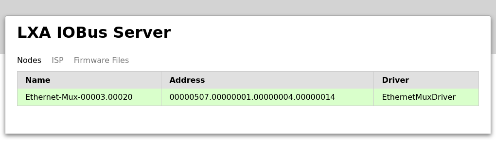
List of nodes in the IOBus Server web interface
Click on a node for detailed information about this node and the options to toggle the outputs.